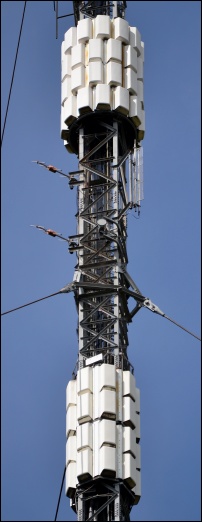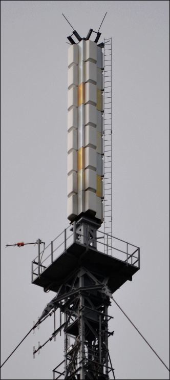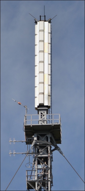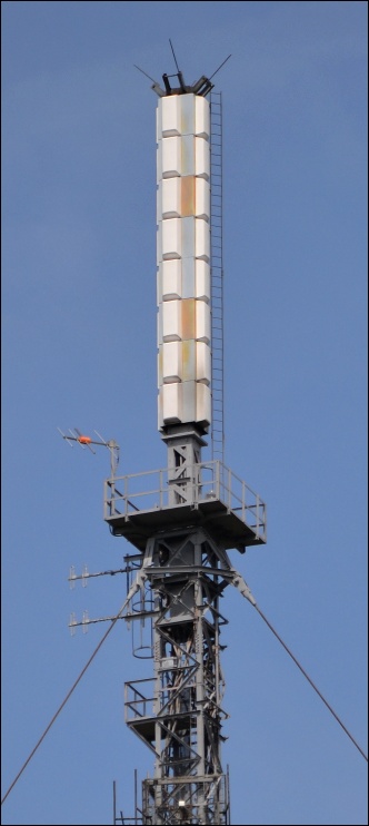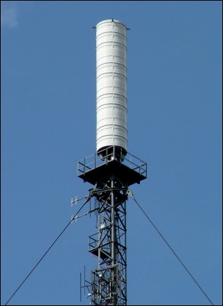
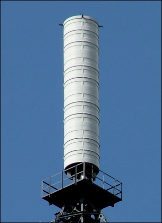
Above: These first two images show the original UHF analogue aerial cylinder.
|
Darvel Home> Aerials> Site Images (740x430 or 930x570 pixels)> Supersize Images> UHF Coverage Map |
|
|
|
|
|
|
|
|
|
Above: These first two images show the original UHF analogue aerial cylinder. |
||
|
|
|
|
|
|
|
|
|
|
|
|
|
|
|
|
|
|
|
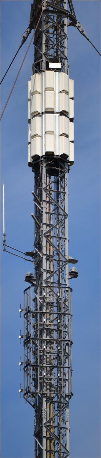
Above: The post-Digital Switchover UHF configuration with the main eight-tier UHF aerial (centre) and the four-tier reserve systems (left and right). The upper of the four-tier arrays was installed for Digital Switchover (replacing an earlier fitting - possibly for analogue Channel 5)) whilst the lower set was pre-existing from the original digital terrestrial multiplexes. Unlike many other masts re-engineered for Digital Switchover, this structure has retained the top platform around the main UHF aerial. |
||||
|
|
|
|
|
|
|
|
|
|
|
|
|
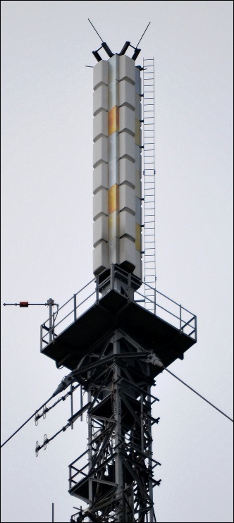
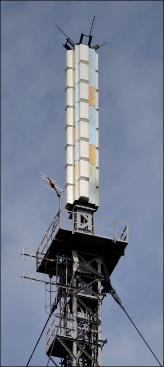
The next six images show the new main UHF antenna in more detail. |
||
|
|
|
|
|
|
|
|
|
|
|
|
|
|
|
|
|
|
|
|
|
|
|
|
|
|
|
|
|
|
|
|
|
|
|
|
|
|
|
|
|
|
|
|
|
|
|
|
|
|
|
|
|
|
|
|
|
|
|
|
|
The following three images follow down from the FM Band II and main DAB radio antennas to the lower of the two four-tier UHF arrays. |
||
|
|
|
|
|
|
|
|
|
|
|
|
|
|
|
|
|
|
|
|
|
|
|
|
|
|
|
|
|
|
|
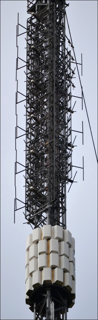
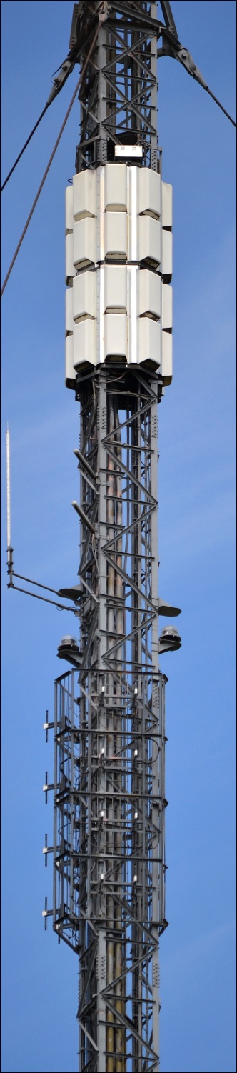
The last four images below cover the section from the UHF reserve aerials down to the Digital One DAB radio installation. |
||
|
|
|
|
|
|
|
|
|
|
|
|
|
|
|
|
|
|
|
|
|
|
|
|
|
|
|
|
|
|
|
|
|
|
|
|
|
|
|
|
|
Darvel Home> Aerials> Site Images (740x430 or 930x570 pixels)> Supersize Images> UHF Coverage Map |
|
|
|
|
|
|
|